Methodology for lens transmission measurement in the 8-13 micron waveband: Integrating sphere versus camera-based
Article shared under SPIE's Green Open Access Policy. Available here.
Authors: Norbert Schuster, Jan Verplancke, Bergeron Salethaiyan, John Franks, Umicore Electro-
Optic Materials (Belgium)
ABSTRACT
Transmission is a key parameter in describing an IR-lens, but is also often the subject of controversy. One reason is the misinterpretation of “transmission” in infrared camera practice. If the camera lens is replaced by an alternative one the signal will be affected by two parameters: proportional to the square of the effective aperture based F-number and linearly to the transmission. The measure to collect energy is defined as the Energy Throughput ETP, and the signal level of the IR-camera is proportional to ETP.
Most published lens transmission values are based on spectrophotometric measurement of plane-parallel witness pieces obtained from coating processes. Published aperture based F-numbers derive very often from ray tracing values in the onaxis bundle.
The following contribution is about transmission measurement. It highlights the bulk absorption and coating issues of infrared lenses. Two different setups are built and tested, an Integrating Sphere (IS)-based setup and a Camera-Based (CB) setup. The comparison of the two principles also clarifies the impact of the F-number.
One difficulty in accurately estimating lens transmission lies in measuring the ratio between the signal of ray bundles deviated by the lens under test and the signal of non-deviated ray bundles without lens (100% transmission). There are many sources for errors and deviations in LWIR-region including: background radiation, reflection from “rough” surfaces, and unexpected transmission bands. Care is taken in the set up that measured signals with and without the lens are consistent and reproducible.
Reference elements such as uncoated lenses are used for calibration of both setups. When solid angle-based radiometric relationships are included, both setups yield consistent transmission values.
Setups and their calibration will be described and test results on commercially available lenses will be published.
Keywords: Transmission, Aperture based F-number, Thermal Infrared, GASIR, Integrating Sphere, Camera Signal
1. MOTIVATION
Transmission is a key parameter in describing a lens, but it is also often the subject of controversy. Engineers are searching for optical reasons of signal degradation on camera. The generated signal at the camera is a superposition of two fundamental lens parameters: the effective aperture based F-number RF1, and the transmission τ in the waveband. Both determine the thermal resolution of an IR-system:
![]()
Other measures with impact on Noise Equivalent Temperature Difference NETD are defined by detector, frame rate and camera electronics2.
The reciprocal of ratio in Equ. (1) is the Energy Throughput (ETP) of imaging optics: The illumination in the center of imaging device is proportional to
![]()
Other measures having impact on illumination depend on the imaged object itself3.
Neither RF nor τ are easy to measure. Often, published values are derived from theoretical results. RF is a value generated from the “Working F-number”4 of ray tracing in the on axis bundle, τ is calculated from spectrophotometric measurements of plano parallel witness pieces obtained in the coating process. This methodical discrepancy generates differences in the expected camera signal S ~ ETP.
A first step to analyze optical reasons of signal degradation on camera is the comparison of two methods for τ-measurement. The Integrating-Sphere-method works well in the visible spectrum5. Its transfer to thermal infrared generates some difficulties which restrict the method’s universality6. The camera-based method corresponds to the empirical measurements generated by exchange of lenses and comparing camera signals.
2. INTEGRATING-SPHERE-(IS)-METHOD
The principle of using an integrating sphere for LWIR transmission measurement is shown in Fig.1. A NiCr wire (1) is heated to 975°C to act as a blackbody source. The output radiation is chopped to compensate for background radiation. The spectrum is then clipped by an 8-13μm filter (2) before passing through pinhole (3) to convert the spatial profile to that of a point source. Next, a ZnSe collimator lens (4) with its focal point in (3) converts the light cone to a parallel beam. A circular test aperture (5) placed as close as possible to the lens under test (6) reduces parasitic reflections. The transmitted light is then captured by the integrating sphere (7) where the detector MCT 77K-detector (8) measures the incident power and converts it to a linear voltage signal U. The detector MCT 77K-detector is cooled by a liquid N2-dewar (9).

Figure 1: Schematic of integrating sphere-(IS)-based method for measuring transmission in the LWIR
This measurement is performed both with and without lenses in the metal work of the lens under test (6), the ratio of both measurements yields the transmission of the lens system:
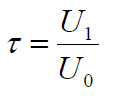
where U0 is the electrical signal without lenses inside the metal work and U1 is the electrical signal with lenses.
The setup above imposes some practical constraints on what can be measured. The maximum ray bundle can be as large as the clear aperture of the collimator lens and its minimum size is defined by the signal-to-noise ratio of the detector.
3. CALIBRATE IS-METHOD
The integrating sphere-based apparatus used for the experiments described here are supplied by Image Science Ltd. and has an accuracy of +/- 1%, with repeatability of +/- 0.5%. Alignment is performed by centering the entire system using visible light at first, then fine-tuning with an infrared camera focused at infinity to properly align the ZnSe collimator. To assess the quality of this alignment, several calibration steps are undertaken. These are outlined below.
In a first step, the setup is checked with uncoated windows of different materials. Here, the theoretical values given by FRESNEL-losses and respecting multiple reflections7 if internal losses are neglected:
Values are mentioned for different materials in Tab. 1.
Table 1: Predicted and measured transmission values of uncoated disks made out of various materials
| Material | Thickness | Test Aperture DT | Follow Equ. (4) | Measured (IS Method) |
| Germanium | 4 mm | 10 mm | 47.0 % | 47.5 % |
| Germanium | 4 mm | 7.5 mm | 47.0 % | 47.0 % |
| Germanium | 4 mm | 5 mm | 47.0 % | 46.5 % |
| GASIR®1 | 1.7 mm | 10 mm | 69.1 % | 68.9 % |
| GASIR®1 | 1.7 mm | 7.5 mm | 69.1 % | 69.6 % |
| GASIR®1 | 1.7 mm | 5 mm | 69.1 % | 70.1 % |
| ZnSe | 1 mm | 10 mm | 71.0% | 71.4 % |
| ZnSe | 1 mm | 7.5 mm | 71.0 % | 71.4 % |
| ZnSe | 1 mm | 5 mm | 71.0 % | 71.3 % |
The results display good agreement with the theoretical values and the accuracy of the apparatus, of +/- 1%, is confirmed for plano-parallel discs. It can clearly be seen that measured transmission values of disks are independent of test aperture used.
The average difference from the theoretical transmission value is 0.4%.
To assess the performance of ray deviating elements, such as lenses, the transmission of several uncoated lenses was measured. The curvature of lens surfaces is not too extreme and the measurement is realized near the optical axis. Under these circumstances, theoretical values are calculated by Equ. (4).
Table 2: Predicted and measured transmission values of uncoated lenses made out of various materials
| Material | Focal length | Lens Aperture DL |
Test Aperture DT | Calculated Equation (4) |
Measured by IS | Calculated Equation (5) |
| ZnSe | 50.8 mm | 28 mm | 10 mm | 71.0 % | 71.9 % | |
| ZnSe | 50.8 mm | 28 mm | 7.5 mm | 71.0 % | 72.4 % | |
| ZnSe | 50.8 mm | 28 mm | 5.0 mm | 71.0 % | 71.9 % | |
| ZnSe | 25.4 mm | 25.4 mm | 10 mm | 67.7 % | 68.9 % | |
| ZnSe | 25.4 mm | 25.4 mm | 7.5 mm | 71.0 % | 68.7 % | 68.9 % |
| ZnSe | 25.4 mm | 25.4 mm | 5.0 mm | 71.0 % | 72.0 % | |
| Germanium | 23.0 mm | 13 mm | 10 mm | 42.9 % | 40.9 % | |
| Germanium | 23.0 mm | 13 mm | 7.5 mm | 47.0 % | 45.2 % | |
| Germanium | 23.0 mm | 13 mm | 5.0 mm | 47.0 % | 46.2% | |
| GASIR®1 | 13.4 mm | 9 mm | 10 mm | 69.1 % | 57.6 % | 66.8 % |
| GASIR®1 | 13.4 mm | 9 mm | 7.5 mm | 69.1 mm | 66.4 % | 66.8 % |
| GASIR®1 | 13.4 mm | 9 mm | 5.0 mm | 69.1 % | 70.4 % | |
| ZnSe | 10.0 mm | 15 mm | 10 mm | 60.4 % | 68.9 % | |
| ZnSe | 10.0 mm | 15 mm | 7.5 mm | 64.0 % | 68.9 % | |
| ZnSe | 10.0 mm | 15 mm | 5.0 mm | 71.0 % | 70.5 % |
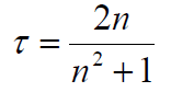
It can be seen that some of the measured values do not agree with the theoretical predictions given by Equ. (4). Analysis indicates that there are two different issues, the test aperture DT, and the focal length (or the optical power) of the lens. The measured transmission-values are closer to the theoretical one given by Equ. (4) at smaller measuring apertures DT. The reason is the curvature of lens surfaces which prevents multiple reflections. Therefore, at the limit, for larger measuring apertures DT, measured transmission is close to a theoretical value without multiple reflections8:
![]()
This value follows by multiplying the transmittance of each surface (1-R) where R is the reflectance accordingly FRESNELrelations. The last column in Tab. 2 mentions these values where they become relevant.
The impact of optical power is shown in Fig. 2. The average absolute transmission differences in relation to theoretical values are plotted against the optical power of the lens. Transmission differences of measuring apertures 5, 7.5 and 10 mm are respected.

Figure 2: Averaged absolute transmission differences versus optical power in dioptre
The disc measurements from Tab. 1 (optical power zero, reference Equ. 4) are very stable. However, increasing optical power generates increasing differences to theoretical values. Equ. (5) becomes the more reasonable reference for lenses with an optical power greater than 40 dioptres, which is a focal length less 25mm.
The optimal measuring aperture for each lens is mentioned in Tab. 2 by bold IS-values. It’s the challenge of this measuring principle: chose the optimal measuring aperture DT.
4. CAMERA-BASED-(CB)-Method
Camera-based methods of transmission measurement rely on the difference in responsivity between a lens and a clear air aperture. Responsivity of a lens is defined as S = ΔU / ΔT where ΔU is the difference in measured signal between a hot and cold reference body and ΔT is the temperature difference between hot and cold reference body. The cold reference body measurement is performed to correct for radiation originating from the lens housing etc.

Figure 3: Radiometric setup in CB-method: left without lens (subscript air), right with lens under test (subscript lens) 1 reference body, 2 FPA measuring incoming flux, 3 emitted flux by reference black body generates radiance L (cold or hot), 4 cover limiting ray bundles, 5 emitted flux of cover generates housing radiance LH, 6 lens under test, u’ aperture angle,
The signal U from each measurement is proportional to the incoming flux Φ. This flux is composed of two contributions, namely the radiation originating from the housing (subscript H) and the radiation originating from the reference body (subscript cold, hot). For each of the four measuring situations follow3:
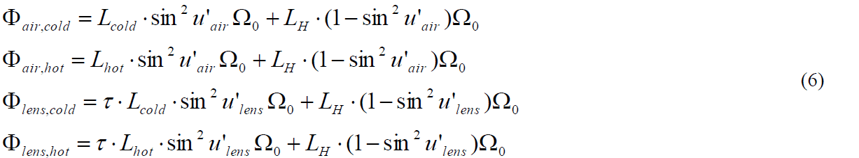
The first term in each equation represents the flux originating from the reference body, where the sin² factor is the projected solid angle of the aperture as seen from the FPA-center. Ω0 is the solid angle in Steradians. The second term is the contribution from the housing, which subtends the rest of the half-sphere: 1 = sin2u’ where u’ = 90o.
The transmission follows after eliminating like terms by

from which lens transmission can be calculated after scaling with the aperture based F-number RF = 1 / 2 sin u'. It is
important to note that this F-number must be used rather than the traditional F-number: The traditional F-number TF, familiar from photography, is the ratio of the focal length to the diameter of the entrance pupil. In the paraxial approximation this is equivalent to RF, however, both values diverge at F-numbers < 1.5. The aperture based F-number bases on the relation for the collected flux.
Application of Equ.(7) supposes that the waveband range is constant for measurements of both air and lens. It is
recommended to use a bandpass filter to achieve this for practical measurements.
5. CALIBRATE CB-Method
The camera-based method uses a 17micron-VGA-bolometer-camera-core from FLIR without any internal noise compensation. Incoming flux will be modulated by a mechanical chopper near to the FPA-plane. The coating of the detector window limits the spectral range of the reference flux Φair.
Table 3: Predicted and measured transmission values of uncoated disks made out of various materials
| Material | Thickness | Aperture angle air | Aperture angle lens | Calculated Equation (4) |
Measured by CB |
| Germanium | 4 mm | 19.6° | 19.6° | 47.0% | 46.9% |
| GASIR®1 | 1.7 mm | 19.6° | 19.6° | 69.1% | 70.6% |
| ZnSe | 1 mm | 19.6° | 19.6° | 71.0% | 71.5% |
The results display good agreement with the theoretical values although it shows greater variability than the IS-method. The averaged difference to the theoretical transmission value is 0.7%. This is more than the IS-measurement but sufficient for the purpose of transmission measurement.
To assess the performance of ray deviating elements, such as lenses, the transmission of several uncoated lenses were measured.
Table 4: Predicted and measured transmission values of uncoated lenses made out of various materials
| Material | Focal length | Aperture angle air |
Aperture angle lens |
Calculated Equation (4) |
Calculated Equation (5) |
Measured by CB |
| ZnSe | 50.8 mm | 14.7° | 14.7° | 71.0% | 68.9% | 69.2% |
| ZnSe | 25.4 mm | 22.2° | 22.2° | 71.0% | 68.9% | 66.6% |
| Germanium | 23.0 mm | 19.6° | 18.7° | 47.0% | 40.9% | 43.8% |
| GASIR®1 | 13.4 mm | 19.6° | 17.3° | 69.1% | 66.8% | 68.6% |
| ZnSe | 10.0 mm | 53.1° | 53.1° | 71.0% | 68.9% | 69.4% |
The lens results are arranged by increasing optical power. The results show a good correspondence with the calculated theoretical values, in that all measured values (except one) are between theoretical values calculated by Equ. (4) and Equ. (5). Table 4 refers also two different principles of measurement: If both angles are equal then the same lens mount is used without lens (air measurement) and with lens (lens measurement). This approach is not optimal for serial tests. Different angles correspond to measurement with one reference body (air measurement) whereby lens under test (lens measurement) has a different aperture angle.
6. SMALL LENS DIAMETER MEASUREMENTS
Single lens designs in infrared with short focal length have small lens diameters. This generates additional alignment problems for transmission measurement.
In the IS-method, it could be avoided when a larger test bundle (diameter DT) is used than actual lens diameter DL. Then, the
incoming flux, without the lens is too high, and the ratio in Equ. (3) must be corrected by areas of the incoming bundles:
![]()
Table 5 shows an example of this correction and demonstrates the impact of test aperture position.
Table 5: Hard coated GASIR®1-lens “Sample 1” with focal length 6.75 mm and lens diameter 5 mm
| Test Aperture DT | Position of Test Aperture | U0 in V | U1 in V | τ measured by IS |
| 10 mm | near collimator | 6.478 | 1.191 | 80.5% |
| 7.5 mm | near collimator | 3.642 | 1.202 | 81.5% |
| 5.0 mm | near collimator | 1.628 | 1.216 | 78.1% |
| 3.0 mm | near collimator |
0.573 |
1.171 | 45.0% |
| 10 mm | near Sample 1 | 6.289 | 1.191 | 82.2% |
| 7.5 mm | near Sample 1 | 3.569 | 1.189 | 81.3% |
| 5.0 mm | near Sample 1 | 1.604 | 1.127 | 76.2% |
| 3.0 mm | near Sample 1 | 0.622 | 0.542 | 87.1% |
It follows that we can be confident in the results for Test Apertures of diameters 10 mm and 7.5 mm. For these apertures the averaged transmission is (81.4 +/- 0.7)% which corresponds to the accuracy of the IS-installation. The Test Apertures with diameters of 5 mm and 3 mm generate much higher fluctuations and make the system more sensitive to the Test Aperture positioning. The standard deviation of these four transmission values is 18.3%. This highlights a critical point of IS-measurement, which is to choose the optimal diameter of test aperture DT.
The same example is analyzed by the CB-method in Fig. 3. It shows transmission results (against a reference mount without lens) for different defocus positions of the lens under test. Using a polynomial approximation of all measured values, the transmission on focus is 81.1%, which is in good agreement with the IS-value.

Figure 3: Measured transmission of “Sample 1” by CB-method in dependence of defocus, second y-axis sin2u’
Figure 3 shows also the impact of focusing position. By trend, the measured signal decreases with increasing distance between FPA-plane and lens under test. The line in Figure 3 indicates the change of solid angle versus defocus. Values sin2u’ are mentioned on right y-axis. Obviously, the main reason of signal change is the decreasing solid angle with increasing defocus.
Table 6 compares transmission values of different lens assemblies. They all contain two GASIR®1-lenses with the stop between. The mentioned RF-values are based on the relative illumination procedure in the ZEMAX-code. This is an averaged value around optical axis. This procedure accounts for the projected solid angle which determines the irradiation on the FPA-plane.
Table 6: Tested two lens assemblies with short focal lengths by both methods
| Focal length | Front-lens Coating | RF | Front-lens Aperture DL | Test Aperture DT | τ measured by IS | τ measured by CB |
| 5 mm | iDLC | 1.27 | 4.0 mm | 3 mm | 86.6 % | 88.5 % |
| 6.8 mm | iDLC | 1.41 | 4.8 mm | 7.5 mm & 10 mm | 82.4 % | 82.4 % |
| 8.5 mm | iDLC | 1.24 | 6.8 mm | 7.5 mm & 10 mm | 81.8 % | 79.6 % |
| 9 mm | iDLC | 1.24 | 7.2 mm | 7.5 mm | 77.7 % | 79.8 % |
Both measuring methods deliver similar transmission values. Obviously, there exists an optimal relationship between test aperture diameter DT for IS-measurement and the front-lens diameter of the assembly in case of small lens diameters, near the clear aperture of the lens.
7. MEDIUM AND LONG FOCAL LENGTH MEASUREMENTS
Table 7 compares transmission values of lens assemblies having a larger entrance lens than the test aperture diameter DT for IS measurement. They all contain GASIR®1-lenses with the stop between. Both measuring methods deliver similar transmission values.
Table 7: Tested two lens assemblies in GASIR®1 with medium focal lengths by both methods
| Focal length | Front-lens Coating | RF | Front-lens Aperture DL | Test Aperture DT | τ measured by IS | τ measured by CB |
| 13 mm | iDLC | 1.26 | 10.5 mm | 10 mm | 78.4 % | 76.7 % |
| 18.8 mm | HEAR | 1.26 | 15.3 mm | 7.5 & 10 mm | 88.6 % | 93.4 % |
| 18.8 mm | iDLC | 1.26 | 15.3 mm | 10 mm | 83.3 % | 82.4 % |
| 25 mm | HEAR | 1.21 | 20.9 mm | 5 & 7.5 & 10 mm | 92.6 % | 86.0 % |
| 25 mm | iDLC | 1.21 | 20.9 mm | 5 & 7.5 & 10 mm | 87.3 % | 81.6 % |
Table 7 shows that the choice of test aperture is less critical than for shorter focal lengths. The test apertures mentioned provide equal IS-transmission values.
Long focal length assemblies have front-lens diameters much larger than the measurement ray bundles. This measurement close to the optical axis improves the repeatability of the transmission measurement. Table 8 compares transmission values of different lens assemblies of UMICORE’s standard range9. All of the lenses measured here contain two lenses. Both measuring methods deliver similar transmission values. The test aperture diameter DT chosen for these IS-measurement is 10 mm and is much less than the mentioned front lens aperture. The test aperture diameter for IS-measurement in long focal lenses is not critical.
Table 8: Tested two lens assemblies in GASIR®1 with long focal lengths by both methods
| Focal length | Front-lens Coating | RF | Front-lens Aperture DL | Test Aperture DT | τ measured by IS | τ measured by CB |
| 35 mm | iDLC | 1.18 | 30 mm | 5 & 7.5 & 10 mm | 77.2 % | 82.1 % |
| 60 mm | HEAR | 1.26 | 48 mm | 5 & 7.5 & 10 mm | 92.6 % | 87.8 % |
| 60 mm | iDLC | 1.26 | 48 mm | 5 & 7.5 & 10 mm | 77.4 % | 78.1 % |
| 100 mm | HEAR | 1.51 | 67 mm | 5 & 7.5 & 10 mm | 91.4 % | 96.7 % |
Tables 6 to 8 give a first impression about the convergence of both methods in practical use. There is no clear bias between the two methods with IS and CB showing higher values for some lenses. The average of absolute difference between both methods is 3.2%, and the maximum difference is 6.6%. There are still opportunities for improving the accuracy and repeatability of both setups.
8. CONCLUSIONS
Measured transmission values are infrequent for long wave infra-red lenses. Currently it is the common practice to multiply transmission values of witness pieces which leads to overstatement of the system transmission. We have demonstrated two independent methods for the measurement of transmission and both methods show consistent results. They can be used to find transmission issues in assembled lenses for the 8-13micron waveband.
Future work can be undertaken to improve the accuracy and repeatability of both methods. This will include developing guidelines for the choice of key parameters such as the measurement aperture diameter in the IS method and back focal distance in CB method.
Equation (1) shows that the RF-measurement is more relevant for thermal resolution of IR-devices. In the visible part of spectrum, commercial solutions10 exist for the traditional F-number f / DEP. This principle could be also relevant for IR-lenses for uncooled detectors. A dedicated procedure to measure RF together with a stable τ-measurement allows a much clearer analysis of “transmission issues”. These could include issues with bulk absorption, coatings and surface effects.
ACKNOWLEDGEMENTS
Authors would like to thank:
The management team of Umicore EOM (Belgium) for permission to publish.
FLIR Commercial Vision Systems (Goleta) for the loan of equipment and technical support in the preparation of this paper.
REFERENCES
1. Schuster, N., Franks, J., "Challenges, constraints and results of lens design for 17micron-bolometer-Focal Plane Arrays in 8-12micron waveband", Proc. SPIE 8012, 80122B (2011).
2. Gaussorgues, G., [La Thermographie Infrarouge], Tec Doc Lavoisier, Paris, 388 (1984).
3. Schuster, N., Kolobrodov, V. G., [Infrarotthermographie], WILEY-VCH, Weinheim, 139 (2004).
4. ZEMAX, [Users manual], 64 (2013).
5. Transmissionsmessung an strahlformändernden optischen Komponenten http://www.ptb.de/cms/index.php?id=644 (2014).
6. INFRA-RED TRANSMISSION SYSTEM http://proddownloads.vertmarkets.com.s3.amazonaws.com/download (2014).
7. Naumann, H., Schröder, G., [Bauelemente der Optik], Carl Hanser Verlag, München, 251 (1987).
8. Schuster, N., Kolobrodov, V. G., [Infrarotthermographie], WILEY-VCH, Weinheim, 110 (2004).
9. http://eom.umicore.com/en/optics/products/GASIRassemblies/ (2013).
10. Blendenzahlmessgerät http://www.oeg-messtechnik.de/?p=7 (2014).